نوشته شده توسط : Likaibin

This section describes how to navigate the Diagnostics interface and select test options of Autel Maxisys Ultra.

Diagnostics Screen Layout

The Diagnostics screens typically includes six sections.

MaxiSys-Ultra-Diagnostics-Screen-Layout-1

1. Diagnostics Toolbar
2. Current Directory Path
3. Status Information Bar
4. Navigation Bar
5. Main Section
6. Functional Buttons

1. Diagnostics Toolbar

The Diagnostics Toolbar contains buttons that allow you to print or save the displayed data and perform other operations. The table below provides a brief description for the operations of the Diagnostics toolbar buttons:

MaxiSys-Ultra-Diagnostics-Screen-Layout-2
MaxiSys-Ultra-Diagnostics-Screen-Layout-3

To print data in Diagnostics
1. Tap the Diagnostics application button on the MaxiSys Job Menu. The Print button on the diagnostic toolbar is available throughout the Diagnostics operations.
2. Tap Print and a drop-down menu displays.
a) Print This Page – prints a screenshot copy of the current screen.
b) Print All Data – prints a PDF copy of all displayed data.
3. A temporary file will be created and sent via the computer to the printer.
4. When the file is sent, a confirmation message displays.

Current Directory Path
The Current Directory Path shows all directory names to access the current page.

Status Information Bar
The Status Information Bar at the top of the Main Section displays the following items:
1. VCMI Icon – indicates the communication status between the tablet and the VCMI device.
2. Battery Icon – indicates the battery status of the vehicle.

Navigation Bar
The Navigation Bar on the left side of the screen displays the main menu of the diagnostics functions. The main menu varies by the vehicle being tested. The common menu includes Auto Scan, Control Unit, Hot Function, Service, Vehicle Profile,Programming and more.

Main Section
The Main Section varies depending on the stage of operations which shows vehicle identification selections, the main menu, test data, messages, instructions and other diagnostic information.

Functional Buttons
The type of Functional Buttons displayed at the bottom of the screen vary by operation. Function include navigation, reporting and code clearing. The functions of these buttons will be described in the following sections when relevant.
The table below provides a brief description of the Functional Buttons’ operations:

NOTE:
Make sure the tablet and the printer are connected either by Wi-Fi or LAN before printing.
For more instructions on printing, see Printing Settings on page 256 for details.

MaxiSys-Ultra-Diagnostics-Screen-Layout-4
MaxiSys-Ultra-Diagnostics-Screen-Layout-5

Select one of the system modules from the Topology or List, and tap Enter System to enter the specific system functions.

NOTE:
The Diagnostic Buttons Toolbar (located on the top of the screen) will be active throughout the diagnostic session for such tasks as printing and saving the displayed data, obtaining help information, or performing data logging.

2. Screen Messages

Messages display when additional input is needed before proceeding. There are mainly three main types of on-screen messages: Confirmation, Warning, and Error.

*  Confirmation Messages
This type of messages usually displays as an “Information” screen, when you are about to perform an action that cannot be reversed or when an action has been initiated and your confirmation is needed to continue.
When a user-response is not required, the message displays briefly.

*  Warning Messages
This type of messages displays when completing the selected action may result in an irreversible change or loss of data. An example of this message is the “Erase Codes” message.

*  Error Messages
Error messages display when a systemic or procedural error has occurred. Possible errors include cable disconnection and communication interruption.

3. Making Selections

The Diagnostics application is a menu-driven program that presents a series of options one at a time. As you select from a menu, the next menu in the series displays. Each selection narrows the focus and leads to the desired test. Use your fingertip or the stylus pen to make menu selections.


:: برچسب‌ها: MaxiSys Ultra ,
:: بازدید از این مطلب : 119
|
امتیاز مطلب : 0
|
تعداد امتیازدهندگان : 0
|
مجموع امتیاز : 0
تاریخ انتشار : یک شنبه 23 شهريور 1399 | نظرات ()
نوشته شده توسط : Likaibin

Before operating or maintaining the Autel Maxisys Ultra, please read these instructions carefully, paying extra attention to the safety warnings and precautions . Use this unit correctly and with care. Failure to do so may cause damage and/or personal injury and will void the limited product warranty.

WARNING: The MaxiFlash VCMI is compatible with Autel main cable V2.0 and USB cable V2 only.

1. Connet the main cable V2.0 to the vehicle Date Conntctor on the VCMI unit, and tighten the thumb screws.

How-to-Connetct-AUTEL-MAXISYS-ULTRA-1

2. Connect the cable’s 16-pin adapter to the vehicle’s DLC, which is generally locater under the vechicle dash.

How-to-Connetct-AUTEL-MAXISYS-ULTRA-2

3. Power up the Display Tablet. Ensure the tablet has a charged battery or is conneted to the DC power supply.

How-to-Connetct-AUTEL-MAXISYS-ULTRA-3

4. Select one of the three methods shown below, Bluetoolth, WI-FI or USB cable V2, to connect the Display Tablet with the VCMI device and estabilsh a communication link. Use only the USB cable connection when programming.

How-to-Connetct-AUTEL-MAXISYS-ULTRA-4

5. When the VCMI device is properly connected to the vehicle and the Display Tablet, the VCMI status button at the bottom bar on the screen shows a green mark, indicating the system is ready to start vehicle diagnosis.

How-to-Connetct-AUTEL-MAXISYS-ULTRA-5

6.The measurement application enables testing of electrical wiring,circuits,and systems.

How-to-Connetct-AUTEL-MAXISYS-ULTRA-6


:: برچسب‌ها: Autel Maxisys Ultra ,
:: بازدید از این مطلب : 125
|
امتیاز مطلب : 0
|
تعداد امتیازدهندگان : 0
|
مجموع امتیاز : 0
تاریخ انتشار : یک شنبه 23 شهريور 1399 | نظرات ()
نوشته شده توسط : Likaibin

Very pleased with SD Connect C4 when plugging it into my van (2002 311 CDI LWB UK spec) to run a ‘quick test’, first attempt and found everything simple to navigate.

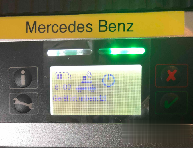
Questions: where does the multiplexer get power from as a battery icon appeared in the little window on the multiplexer and a warning !Check Batteries! after this appeared an error screen appeared on the laptop screen along the lines of communication had been disrupted (i was checking the block heater at the time) due to low voltage.

I had the van idling in the driveway with 14.2v in the top right of laptop screen so wanted to know as to how if atall i charge the multiplexer, the laptop had 82% battery life when the ! Check batteries! appeared on the multiplexer.

sdconnect-check-batteries-solution-01 (2) sdconnect-check-batteries-solution-05 (2)

Possible reason:

Multiplexers SDConnect C4 Chinese production is peculiar, randomly appearing, battery charge error. The error is accompanied by the message “Insert / check batteries” “batteries can not be charged” on the instrument display.

This stops the batteries from charging. This error can be caused by two reasons.

wear or not the corresponding capacity of the installed batteries.
a chaotic error caused by the feature of the circuit design of the multiplexer. Revision of the device circuitry eliminates the second reason. As a result, the battery charge error will appear only due to the “fault” of the batteries themselves.
How to solve ” Check Batteries!” error?

Review 1:

I am pretty sure that the consensus view is to run it without batteries and ignore the warning on the display.

BTW: you should always connect an external power supply to your van while using Star.

Another thing to watch out for is to NOT use a 12v-to-laptop adapter powered by the Sprinter when you’re using a diagnostic device that also connects to the Sprinter.

Many 12v-to-laptop devices have a “common positive” .. the battery’s +12v is fed directly to the laptop via a wire.
The 12v-to-laptop adapter then creates the laptop’s desired 18v by pushing the *negative* feed “down” an addition 6 volts …
If the SD Connect C4 diagnostic device expects to be able to connect the laptop’s signal “ground” (or 0v or negative) directly to the Sprinter’s 0v/negative/frame smoke can happen… you’ve suddenly got the power adapter fighting the two “negatives’” 6 volt difference across the diagnostic device.

You can avoid this problem by letting the laptop only use its internal battery, or by using a 120vac adapter to power the laptop.(or the 12v-to-laptop plugged into a totally separate external battery).

Review 2:

Try to use mux on lan(without wireless card inserted),and you will have no more ‘check batteries’ error on display.
seems that error came from heating the wifi card and not correctly drainage from hot air.

Added to this, using mux without wifi card save around 0.4v consumption, xentry will see around 0.4v more voltage,so safer voltage for programming,etc… I dont have wifi card installed, better work always with lan, i dont see too much work in connecting just a cable when making a work.

i think heat with wifi card is a problem because card itself is heating adding to the heat that pcb’s itself produces, with no card installed less heat inside the mux and heat can go exit through the free slot of card, making a grill on the grey plastic piece will help allowing heat to go out of mux, surely extending its life.

Review 3:

I’ve used my (Chinese clone C4) MUX from the first beginning without batteries.
After some time I inserted rechargeable batteries just because I had the same idea as mentioned a few times above -> The voltage drop/peak when starting/stopping the cars engine is not good for the electronic components of the mux. The same problem occurs when disconnecting the mux from the car.

But as I did not remove the rechargeable batteries after use I noticed that some of the inserted batteries went dead after a while. This was (my personal opinion) because of the continuous battery drainage that pulled the voltage so low the batteries eventually got broken.

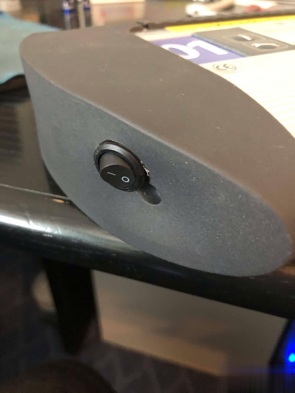
I always had with empty batteries often because the device was in standby mode and in the course of time were empty, I have considered a solution and indeed an on and off switch after the device goes down in standby mode, I turn it off thus it can not consume power and keep the batteries.

sdconnect-check-batteries-solution-06-1 (2)

Another solution I’m thinking about is when not in use connecting the mux to a power source (battery charger). This way the batteries are always getting charged but I’m not sure if this is a good idea?

And I never use the WiFi connection because I’m afraid for connection losses during updating work on the car.
Just my humble opinion in this matter.

Good to know:

1). When testing the Mercedes Benz cars:

All sdconnect c4 don’t need the battery.

2). When updating sdconnect c4 firmware:

– Only the best sdconnect C4 plus DoIP  does not need the battery:

– The other sdconnect c4 firmware update needs to install the battery.

SD Connect C4 battery installation instructions here:

Easy Guide on how to install MB SD C4 Batteries

Credits to @ gcs190 who shares “How to Update SD Connect without batteries“:

If you need to update an SD Connect and you do not have batteries or the power supply/charging circuit is damaged, you only have to edit the toolkit.ini file, modifying the following lines so that the supply and/or battery voltage is lower to the real (it would be enough to set them to zero)

Obviously make sure you have a stable and sufficient external supply.

[SoftwareUpdate]

Voltages necessary for SDconnect firmware updates. These values are only for the pre-check of the toolkit, the values will be checked by the update process again

MinUpdateVoltageVBatt=7200
MinUpdateVoltageVExt=11000

A reboot is required for the new settings to take effect (Probably a Tkserver restart is enough)

Good luck!


:: برچسب‌ها: SD Connect C4 ,
:: بازدید از این مطلب : 111
|
امتیاز مطلب : 0
|
تعداد امتیازدهندگان : 0
|
مجموع امتیاز : 0
تاریخ انتشار : یک شنبه 9 شهريور 1399 | نظرات ()
نوشته شده توسط : Likaibin

Have 2013 Hyundai i40, the key starts the car, put the buttons don’t work, so I’m going to use the OBDSTAR X300 Pro4 to program the key.

obdstar-x300-pro4-programs-hyundai-i40-remote-01 (2)

obdstar-x300-pro4-programs-hyundai-i40-remote-02 (2)

Put into the OBD port.

obdstar-x300-pro4-programs-hyundai-i40-remote-03 (2)

Select from vehicle.

obdstar-x300-pro4-programs-hyundai-i40-remote-04 (2)

Europe.

obdstar-x300-pro4-programs-hyundai-i40-remote-05 (2)

i40 is here.

obdstar-x300-pro4-programs-hyundai-i40-remote-06 (2)

I can “Select from type”, then “Remote”.

obdstar-x300-pro4-programs-hyundai-i40-remote-07 (2)

16pin obdii connector.

obdstar-x300-pro4-programs-hyundai-i40-remote-08 (2)

Type 1.

obdstar-x300-pro4-programs-hyundai-i40-remote-09 (2)

Program remotes.

obdstar-x300-pro4-programs-hyundai-i40-remote-10 (2)

It says “Switch ignition on and then switch ignition off and remove key, press ENTER to continue.

obdstar-x300-pro4-programs-hyundai-i40-remote-11 (2)

obdstar-x300-pro4-programs-hyundai-i40-remote-12 (2)

Press LOCK or UNLOCK for more than 1 sec.

obdstar-x300-pro4-programs-hyundai-i40-remote-13 (2)

Program success, whether to program next one?

Press [Enter] to continue.

obdstar-x300-pro4-programs-hyundai-i40-remote-14 (2)

Esc and it displays ” Program complete”.

obdstar-x300-pro4-programs-hyundai-i40-remote-15 (2)

Power off OBDSTAR X300 PRO4.

Unplug the OBD2 cable and to test the remote.

You see it is working

obdstar-x300-pro4-programs-hyundai-i40-remote-16 (2)

Okay, very good programmer OBDSTAR X300 PRO4.


:: برچسب‌ها: OBDSTAR X300 Pro 4,OBDSTAR X300 Pro4, ,
:: بازدید از این مطلب : 93
|
امتیاز مطلب : 0
|
تعداد امتیازدهندگان : 0
|
مجموع امتیاز : 0
تاریخ انتشار : یک شنبه 9 شهريور 1399 | نظرات ()